INDEX
Getting Started
Heat Load
.....heat loss basics
Floor Output
Floor Covering
Floor Surface Temp.
Average Water Temp.
Supply Water Temp.
Tube Selection and Size
Tube Spacing
Total Tube Required
Tube Circuit Length
Number of Circuits
Actual Circuit Length
Flow Per Tube
Pressure Drop
Summarize Circuits
System Flow
System Pressure Drop
USE THE RadPad© and 'WORKSHEET' to complete the system sizing.
14. Flow Per Tube
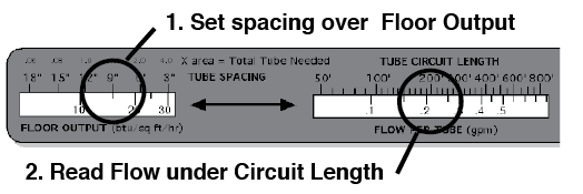
Scroll the slide on SIDE B of the RadPad© calculator to set the FLOOR OUTPUT at the TUBE SPACING. Read the FLOW PER TUBE under the TUBE CIRCUIT LENGTH.
example:
put 15 btu/sq ft/hr under 9" o.c. spacing
read .22 gpm flow per tube under 206' circuit length
15. Pressure Drop
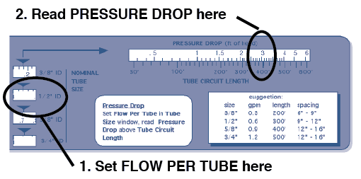
Scroll the slide on SIDE B of the RadPad© calculator to set the Flow Per Tube from step 14 in the CIRCUIT TUBE SIZE window that corresponds with the tube size you selected in step 8. Read the PRESSURE DROP over the TUBE CIRCUIT LENGTH you established in step 13.
Note: At this point you may find the flow or pressure drop is either too low or too high. You can return to step 13 and adjust the number of circuits resulting in longer or shorter circuits; or you can return to step 8 and choose a different diameter tube.
example:
• .22 gpm Flow Per Tube is too small for 1/2"ID
• return to step 13 and reduce to one 412' circuit
• in step 14 find 412' circuit = .44 gpm flowRepeat step 15.
16. Zone Flow
To find the total flow required by a zone, add together the individual flows of each circuit.
Flow Per Tube + Flow Per Tube = Zone Flow (gpm)
example: .44 + .38 + .35 + .40 = 1.57 gpm Zone Flow
17. Zone Pressure Drop
To find the total pressure drop of the zone, start with the highest pressure drop value of a single tube and add the pressure drop in the supply and return lines from the heat source including valves and fittings.
The RadPad© calculator can be used on supply lines which are 3/4" ID or less. (use standard hydronic heating procedures)

