INDEX
Getting Started
Heat Load
.....heat loss basics
Floor Output
Floor Covering
Floor Surface Temp.
Average Water Temp.
Supply Water Temp.
Tube Selection and Size
Tube Spacing
Total Tube Required
Tube Circuit Length
Number of Circuits
Actual Circuit Length
Flow Per Tube
Pressure Drop
Summarize Circuits
System Flow
System Pressure Drop
USE THE RadPad© and 'WORKSHEET' to complete the system sizing.
6. Average Water Temperature
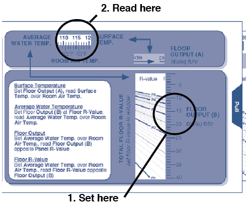
Looking at the front of the Rad Pad© calculator, locate the FLOOR OUTPUT (B) window and pull the slide until your panel output (btus/sq ft/hr) lines up with your FLOOR R-VALUE on the scale. Read the AVERAGE WATER TEMPERATURE above your design ROOM AIR TEMPERATURE.
example:
• set 15 btus/sq ft/hr at 3.21 R-value
• read 118˚F AVERAGE WATER TEMPERATURE above 70˚F ROOM AIR TEMPERATURESIDE A - RadPad© calculator
Tip:
Maximum Water Temperatures
140˚F - tube embedded in concrete or gypsum
160˚F - tube mounted on underside of wood subfloor
180˚F - tube suspended beneath wood subfloor
Always use the lowest water temperature possible to do the job.
7. Supply Water Temperature
As the water passes through the floor, it gives off heat and drops in temperature. To obtain an average water temperature you must begin with a high supply water temperature. Assume a 20˚F drop in temperature from supply to return. Add 1/2 of this drop (10˚F) to the Average Water Temperature.Average Water Temperature + 10˚F = Supply Water Temperature
example: 116˚F Average Water Temperature + 10˚F = 126˚F Supply Water Temperature
This is the high limit temperature setting for the boiler, water heater, mixing valve or whatever supply temperature control is being used.
