INDEX
Getting Started
Heat Load
.....heat loss basics
Floor Output
Floor Covering
Floor Surface Temp.
Average Water Temp.
Supply Water Temp.
Tube Selection and Size
Tube Spacing
Total Tube Required
Tube Circuit Length
Number of Circuits
Actual Circuit Length
Flow Per Tube
Pressure Drop
Summarize Circuits
System Flow
System Pressure Drop
USE THE RadPad© and 'WORKSHEET' to complete the system sizing.
5. Floor Surface Temperature
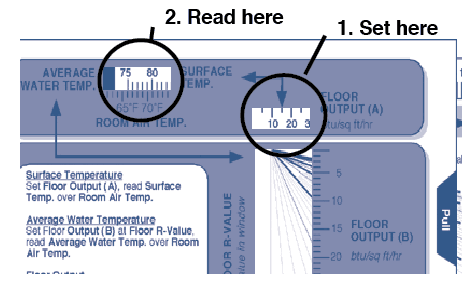
Viewing SIDE A of the RadPad© calculators scroll to the right until your floor output (calculated from the heat loss) appears in the FLOOR OUTPUT (A) window.
With this number centered in the window, read the floor SURFACE TEMPERATURE directly above the ROOM AIR TEMPERATURE which you used in doing your heat loss calculations.
example:
• set 15 btu/sq ft/hr in FLOOR OUTPUT (A) window
• locate 70˚F ROOM AIR TEMPERATURE on scale
• read 79˚ F floor SURFACE TEMPERATURE directly above 70˚FSIDE A - RadPad© calculator
Tip:
Maximum Floor Surface Temperatures
85˚F - areas of prolonged foot contact like living rooms, kitchens, family rooms and commercial office buildings.
90˚F- areas where warm floors are preferred like bathrooms, entries, and room perimeters.
Wood Floors - temperature can affect the moisture content of wood floors. The lower the temperature, the better. Wood floors, when properly installed in a humidity controlled environment, can tolerate most normal radiant floor temperatures.
